97 Results
View results:
Sort by:
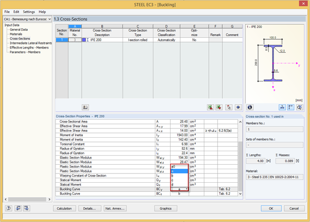
You can adjust the buckling curve of a cross-section in RF-/STEEL EC3, if necessary. This can be done in Window 1.3, Cross‑Sections.
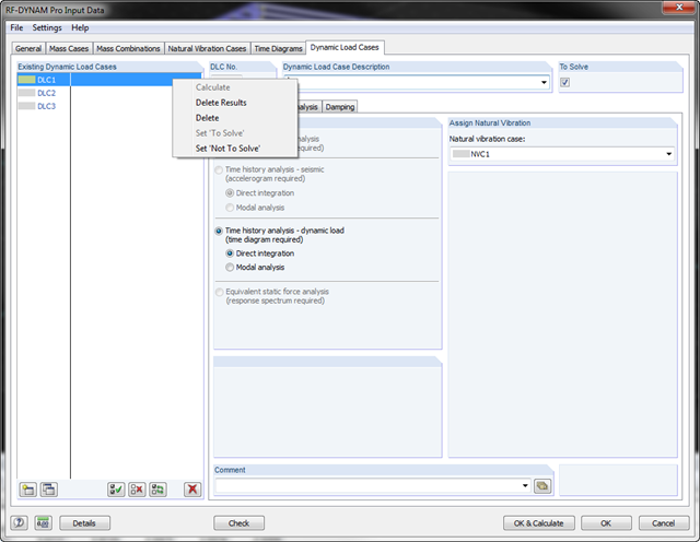
In RF-/DYNAM Pro, you can now keep the existing results. For example, if you work with several dynamic load cases, you can calculate or modify the individual dynamic load cases while retaining the unchanged results of the other dynamic load cases.
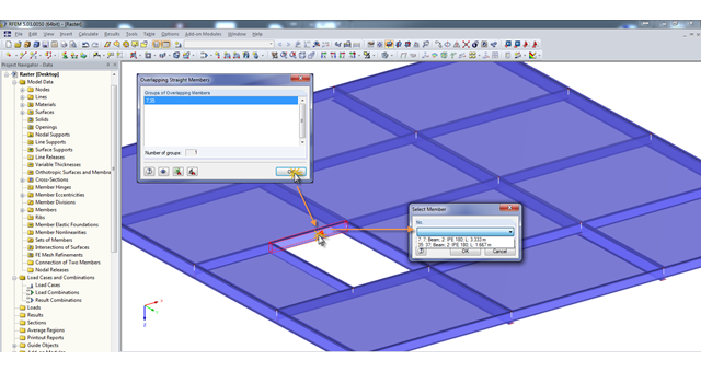
A modell check allows you to find overlapping members, among other things. However, this targeted selection could cause some minor problems. Therefore, there is a selection window now available, which appears when you click on one of the elements. This appears by clicking on one of the elements. Additional information helps you to select the correct member.
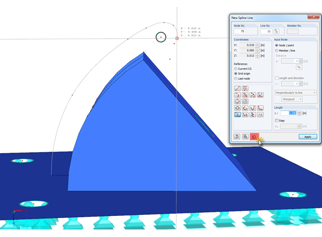
In RFEM, if you want to display a curved geometry (preferably in one continuous line), you can use splines or NURBS, for example. When modeling, you should pick the individual nodes one after another. If a mistake is made, you can go back using the special Undo function in the "New Spline Line" window. Thus, it is not necessary to enter the entire continuous line again.

With the "Info About Object..." function available in the menu under "Tools", you can display all the information about an object by placing the cursor on it in the graphical window.
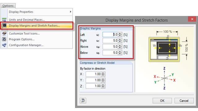
Sometimes, a model in the graphic window is displayed without filling the entire window, or with overly large margins after clicking the [Show Whole Model] button. To set the size of the graphic margins, click "Options" → "Display Margins and Stretch Factors". The value specifies the percentage of the margin relative to the graphic window size.
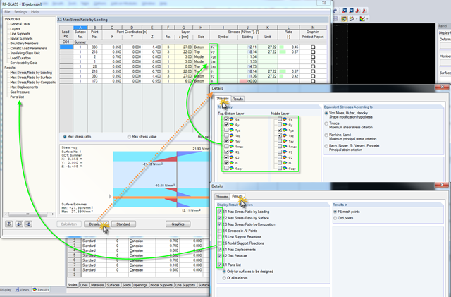
Click the [Details] button in RF-GLASS to select the results to be displayed. In order to get a better overview for the result evaluation, you can select the individual stress graphics (principal stresses, stresses oriented to axes, shear stresses) as well as various result windows. This way, you can show only the results you require.
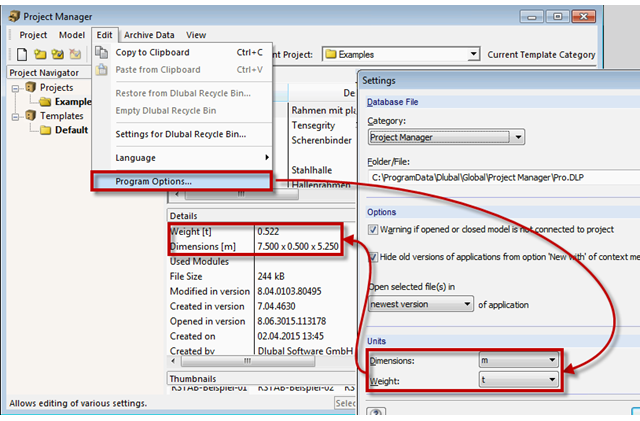
The network-capable Project Manager controls the projects of all Dlubal Software applications in one central location. A table displays the important information for each model and corresponding file. Now, you can set dimension and weight units in the program options.
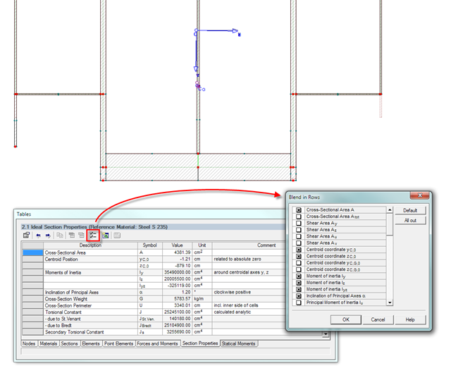
The result window of the cross-section properties can be adjusted individually using the [Filter] button in the table menu bar. You can then activate or deactivate the individual cross-section parameters in the dialog box.

Surfaces can be created using the "Surface via Line Extrusion" function by extruding lines perpendicular to the active work plane. The Video (WMV) shows how to use this function.